Layout Of Hvac System
Layout of hvac system. Small HVAC System Design Guide Overview 1 Overview This Design Guide focuses on packaged heating ventilation and air conditioning HVAC syst ems up to 10 tons per unitthe most common HVAC systems for small commercial buildings in California. The duct pressure increases beyond the set point and the sensor simply signals the fan to reduce RPM to the point where the duct. But ensure that the duct paths give more room for air.
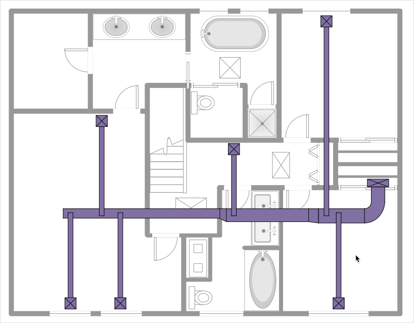
This reflected ceiling plan RCP sample shows lighting and HVAC layout. Ducts are used in heating ventilation and air conditioning HVAC to deliver and remove air. Ventilation is the process of changing or replacing air in any space to control temperature or remove any combination of moisture odors smoke heat dust airborne.
Last but not least the HVAC system is responsible for large portion of building operating costs. Third HVAC systems require significant capital investments. Design Documents ΠInstructions to.
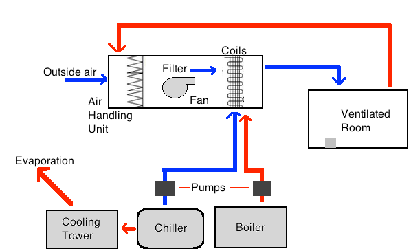
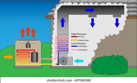
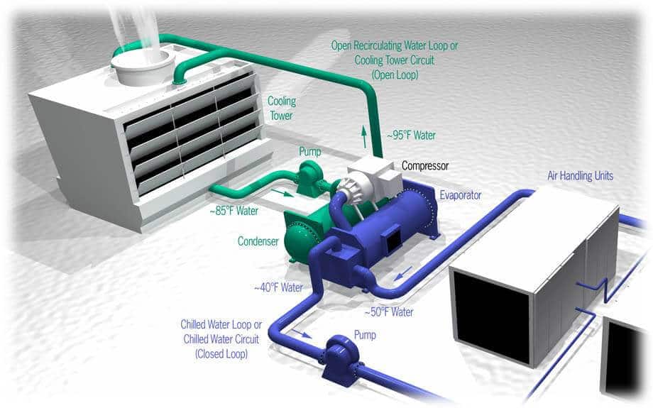
The vector stencils library HVAC equipment contains 26 symbols of HVAC equipment. RCP - HVAC layout. Figure 41 Heat Transfer Loops In Refrigeration System In the Figure 41 thermal energy moves from left to right as it is extracted from the space and expelled into the outdoors through five loops of heat transfer.
Duct sizing for the two examples would certainly be very different. This table represents how much air a certain size duct should handle in a reasonably well-designed system friction rate 010 iwc100ft. There is also an ACCA manual for calculating CFM for your HAVC system.
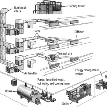
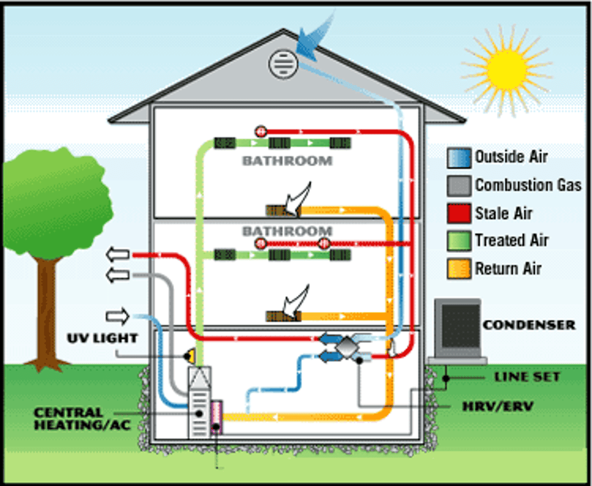
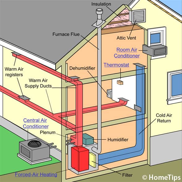
The System Layout ΠCreating the drawings schedules and specifications that fully and accurately describe the HVAC design. The needed airflows include for example supply air return air and exhaust air. In the central air conditioning system all the components are group together in one central room and conditioned air then distributed from the central room to the required places through the extension duct system.
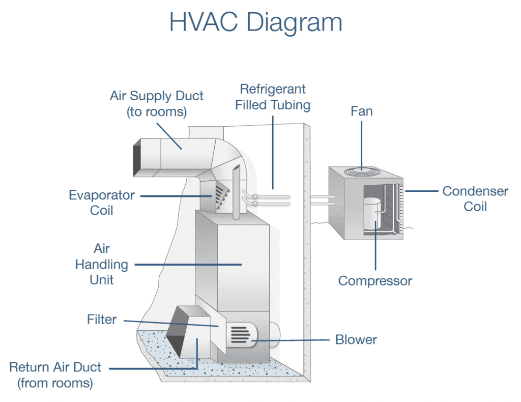
HVAC is an acronym for Heating Ventilation and Air Conditioning. After calculating loads of your HVAC system now come towards the layout of your system.
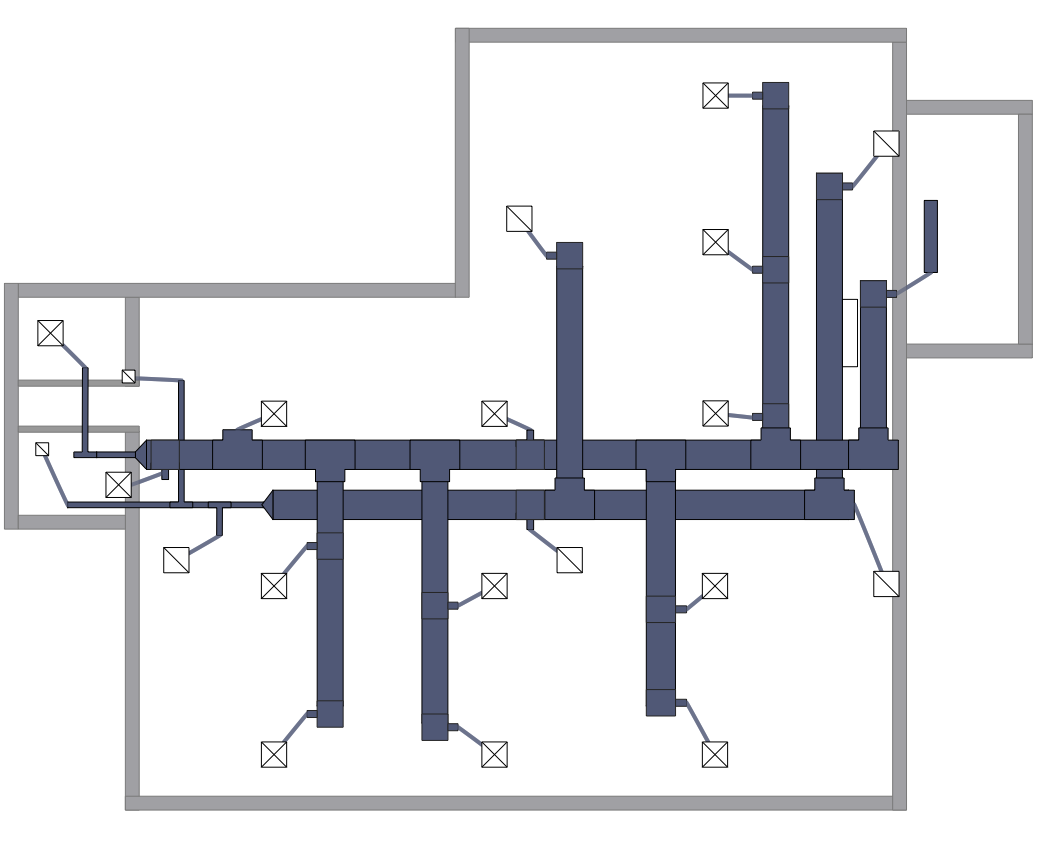
This HVAC floor plan sample depicts the layout of ventilation system air supply and exhaust ductwork.
Sizes and loads are calculated to define the equipment used and a layout is developed for the entirety of the proposed system. Add up all of the flows they should be greater than the target flow from 1. A good HVAC system aims to provide thermal control and indoor comfort and one that is designed using the principles of thermodynamics fluid mechanics and heat transfer. Sizes and loads are calculated to define the equipment used and a layout is developed for the entirety of the proposed system. After calculating loads of your HVAC system now come towards the layout of your system. Figure 41 Heat Transfer Loops In Refrigeration System In the Figure 41 thermal energy moves from left to right as it is extracted from the space and expelled into the outdoors through five loops of heat transfer. The System Layout ΠCreating the drawings schedules and specifications that fully and accurately describe the HVAC design. HVAC Single Line Diagram. Air Handling System ComponentsLayout.
This HVAC floor plan sample depicts the layout of ventilation system air supply and exhaust ductwork. Ducts are used in heating ventilation and air conditioning HVAC to deliver and remove air. After calculating loads of your HVAC system now come towards the layout of your system. Air enters the system from the outside through an air duct and is mixed just before the filters with return air from the space. Last but not least the HVAC system is responsible for large portion of building operating costs. HVAC Single Line Diagram. The boiler is located in the first floor mechanical room and.














Post a Comment for "Layout Of Hvac System"